It’s easy to think of a battery as a bucket full of energy. When we would like some energy, we connect our circuit and pour the energy out. However, this analogy doesn’t account for internal impedance. A better analogy is that batteries are like water bottles. When a water bottle is tipped over, the water cannot flow out freely because a nozzle restricts the flow. Similarly, a battery has internal impedance that restricts the flow of energy due to factors such as age, quality of materials and imperfections in construction. This impedance is not purely resistive in nature, but has capacitive components as well, which presents a challenge for measurement.
The internal impedance reflects the quality of the battery and how well it will perform over its lifespan. A battery that has higher internal impedance will be less efficient and prone to early failure. High internal impedance generates excess heat during operation, which can become a safety issue if a battery goes into thermal runaway. Measuring internal impedance before use is a good way to identify cells that may be at risk of failure. There are several ways to characterize internal impedance and they each characterize an aspect of the performance slightly different.
One technique is electrochemical impedance spectroscopy (EIS). During this test an AC signal is applied to the battery over a wide spectrum of frequencies and the battery’s response is measured. This test can take a long time but gives the fullest picture of impedance behavior within the battery.
The most commonly used method is AC internal resistance (ACIR). Since this an AC technique it characterizes impedance, though typically only the real part or the resistance is kept. ACIR is a subset of the EIS process, with the measurement taken at a single frequency, typically 1 kHz. This characterizes the small signal behavior, which is a good indicator of battery quality and is much faster than the full EIS process. The time savings makes it a popular test in the production space, where every battery must pass a specification.
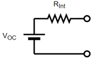
The final method is DC internal resistance (DCIR), which may also be called pulsed characterization. In this method, only the resistive components are measured, as the battery is assumed to be represented by an ideal open circuit voltage and a series resistance as shown in Figure 2:
Figure 2: DCIR Battery Model
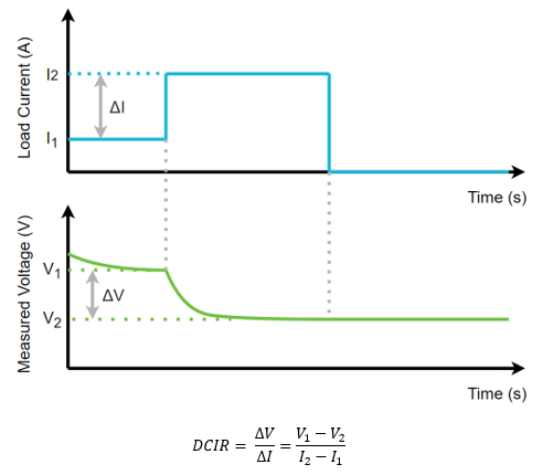
A DC current is applied to the battery for a set amount of time and the change in the battery’s voltage is measured and the resistance calculated. A graph that demonstrates this can be shown in Figure 3.

Figure 3: DCIR Measurement Routine
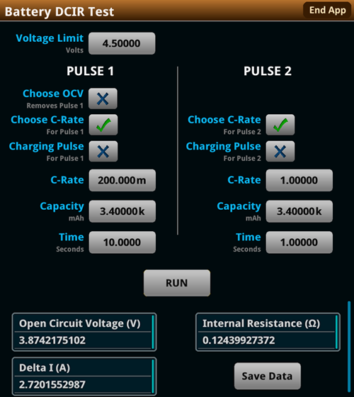
The currents used in the DCIR method are typically much larger than the ACIR method, making this a more realistic test in terms of use case as batteries are often exposed to sudden high current draw. The internal resistance of the battery is the biggest restrictor of a battery’s ability to output large current, so it’s important to identify a battery that cannot perform under high current situations. An instrument that is capable of outputting high current pulses while making synchronized voltage measurements is ideal. Source Measure Units (SMUs) such as the Keithley 2461 are capable of accurately delivering 10 A pulses, while measuring the resulting voltage with 6.5 digit resolution. These SMUs are powered by Test Script Processor (TSP®) enabling users to run a full DCIR pulse sequence and receive calculated data from the front panel using the DCIR TSP App.

Figure 4: Configuration and results of DCIR test on a Keithley 2461 Graphical Touchscreen SMU
A battery’s internal impedance is a key indicator of the quality of the battery and how well it will perform over its lifespan. Three methods may be used to measure a battery’s impedance or resistance, and each method gives somewhat different information.
TestEquity are an approved UK partner for Tektronix
Blog: Testing Battery Resistance
Content Source: https://www.tek.com/en/blog/testing-battery-resistance


