

ECE R10 specifies a range of conducted and radiated immunity tests that must be performed on Electric Vehicles. Whilst the standard applies to all cars (EV and conventional powered vehicles), for EV’s there is an additional requirement that the tests should be performed whilst connected to the charging infrastructure. Below is an extract from a webinar, presented by Thomas Handschin (Product Manager AMETEK CTS Switzerland), that discusses the possible options for simulating a charging infrastructure. He talks about the components needed, and the advantages and disadvantages of the different solutions.
“ECE R10, as you may know, is not new. For non electric vehicles it has been around decades.”
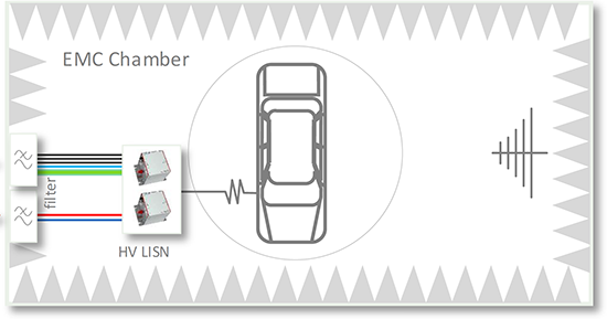
Some of the tests that are defined for non electrical cars, are also relevant for electric cars. The so-called radiated immunity and emission tests. These are performed in an EMC chamber/absorber room, with the EMC, RF equipment also inside.
So, the car is positioned on a rotary table, and then you do all the radiated emission and immunity tests.
This is true for an EV when it’s not in charging mode – when it’s driving – which is exactly the same for a non-electric vehicle.
For EV’s however, some additional tests must be performed during charging. So this means the EMC Chamber has to be equipped with a simulated charging infrastructure.
The charging infrastructure must also be able to charge the car because the test condition specified requires the car to be charged. And also to support the different charging modes and standards.
This is quite tricky, I learned out of experience from many EMC labs that have an EMC chamber for radiated testing. It is quite a challenge for them to retrofit or build a new EMC chambers for the requirements of ECE R10 for electric vehicles.
Here I would like to highlight some challenges and also to illustrate the basic concept.
So the test set-up in the EMC Chamber for the electric vehicle must be able to perform – during charging – radiated immunity and emission testing, and also conducted cable bound measurements and immunity tests.
General test setup and supply – radiated test area
The RF tests are in the higher frequency range, and for the conducted emission measurements and conducted immunity tests, you will require some high voltage LISNs or line Impedance stabilization networks (artificial networks) which are placed inside the test chamber.
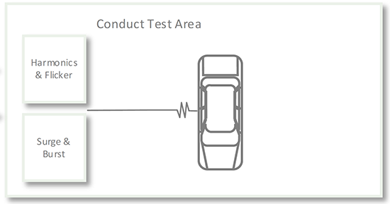
General test setup and supply – conducted test area
For charging, you will require a voltage source which needs to be available in the chamber and the conducted test area where the standard requires additional new tests including Harmonics and Flicker, and Surge and Burst testing.
These tests are typically performed outside of the EMC Chamber, in a so-called conducted test area.
So the supply needs to go to the EMC chamber and to the conducted test area.
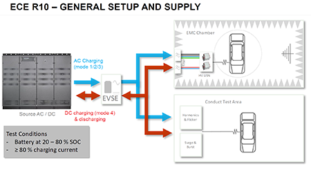
There are different ways of charging an electric car. The ways of charging are called mode – modes 1, 2, 3, 4. Mode 1 2 3 is “AC charging”. For AC charging, the setup is relatively straightforward using a grid simulator or source. Usually, it’s not the grid that is used but some kind of electronic source combined with ESVE (electric vehicle supply equipment) which is usually a charging station simulator. We will see why this is required.
The source provides the AC supply to EVSE and the EVSE provides the AC, supply to the Chamber and the conducted test area.
For DC, it is a very similar setup. There’s DC charging – Mode 4 – which is high power charging. This is a high voltage DC input typically found on highways for fast charging – 30 minutes to get to 80% state of charge.
Since ECE R10 does not differentiate between AC and DC charging, all the tests in the EMC chamber and conducted test area must be performed for Mode 3 (AC) and Mode 4 (DC) charging.
For this a source or grid simulator is required that provides DC power to the charging station simulator. and then the DC power is provided to the EMC chamber and conduct test area.
The test conditions, which are defined an ECR, 10, require the battery state of charge to be between 20 and 80%, and the charging current needs to be higher than 80% for most but not for all of the tests.
This is actually quite a challenge. Because you need to keep the car always, between 20 to 80% state of charge, and it’s impossible to perform all the tests of ECE R10 in one charging cycle.
So imagine, you start charging at 20%. So you start with your RF immunity and emissions tests. And it may be a fast charge through DC. So it takes 30 minutes to get the car batteries at 80%. At which point you need to stop testing because you’re outside of the test condition.
And now the batteries charged how to get rid of the energy? Now, there are several ways to do that.
You can either just drive around in the parking lot, which I actually have seen, you can use a dynamometer on the on the test bench “roll off” the energy.
A third and I think the cleverest way is to discharge the battery through the charging station simulator and the source. This method is much faster with the added advantage of recovering the electrical energy to the grid.
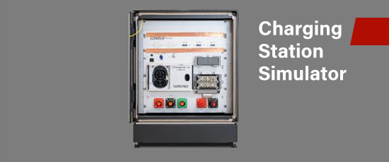
The charging station simulator EVSE can be achieved in two ways for the test setup.
A standard charging station that is commercially available.

or A charging station simulator.
Each of the two solutions have advantages and disadvantage. The advantage of the standard charging station is the lower cost initial investment. This also applies to a DC charging station when compared to the dedicated simulator.
Another advantage is the setup which is typically easier with standard charging blocks and a straightforward user-interface.
And despite the limited functionality it is suitable for many of the required tests. In addition, they are widely available from many charging station suppliers.
The advantage of the charging station simulator, is that it covers a wide range of charging modes and standards to see what that means later.
It also allows discharging which is usually not the case for charging stations, it allows further testing, for example of the protocol, or you can maybe just some parts of the protocol.
An important advantage is the charging simulator can evolve with changes to the standards over time. This provides security and flexibility for your investment.
A charging simulator solution will be EMC proven and a have large range of connection options, as well as being customizable.
In summary, if you’re looking a low cost solution, with limited functionality, I think it’s possible to use a standard charging station for a test setup.
If you’re looking for more functionality and and a proven solution for the application with flexibility for the future, then the Charging Station Simulator is the right choice.
Regarding the charging standards and modes. You can see there are many charging standards in the world for electric vehicles. So if you’re an OEM, or an onboard charger manufacturer, you need to make sure that your car is compliant all around the globe in order to market it in different countries.
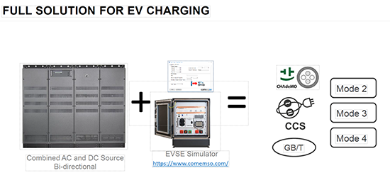
So you need to make sure that supports all the different charging standards and modes – AC and DC.
The ECER10 should be considered as the minimum requirement for your test setup. For this reason, we believe the charging simulator a is better solution and long term investment.
Content Source: https://www.ametek-cts.com/blog/2022/september/ece-r10-testing-power-sources


, for EV’s there is an...)