

Low Current Switching
When switching currents of 1μA or less, special techniques must be used to minimize interferences, such as offset currents, leakage currents, electrostatic interference, triboelectric currents, and electrochemical currents. These types of interferences may be due to the scanner card itself, the connecting cables, or the test fixturing. Allowing sufficient settling time before making a measurement is also crucial when switching low current.
Offset Currents
The offset current specification of the switch card should be as low as possible for switching low current. Offset current is a spurious current generated by a switching card even though no signals are applied. It is usually caused by galvanic sources on the card. Offset current is especially significant when measuring low currents if the magnitude of the offset is comparable to the low current being measured. Scanner cards designed to minimize offset current are commercially available. For example, the Model 7158 Low Current Scanner Card has <1pA offset current (typically <30fA).
To measure the offset of a switch card, connect the output of the card to a picoammeter or electrometer. Make sure all input connections on the scanner card are shielded. If the card has triax or BNC connections, cap each input channel. Close each channel individually and measure the offset current after allowing the switching transients to decay and the current to stabilize. If the offset currents for the different channels are reasonably stable, a correction factor can be stored in the control computer to allow more accurate low current measurements. This is done by subtracting the offset current for a given channel from subsequent measurements made via that channel.
Leakage Currents
Leakage current is an error current that flows through insulators when a voltage is applied. It can be found on the switch card, in the connecting cables, and in the test fixture. Even high resistance paths between low current conductors and nearby voltage sources can generate significant leakage currents. Use a card with high isolation, guard the associated test fixtures and cables, select proper insulating materials, and clean the circuit boards to reduce these effects.
To minimize extraneous current paths (or leakage current), use a switch card that has high channel isolation resistance (the isolation between channels). When switching a current to be measured, high input isolation (the isolation between input HI and LO), is not as critical as channel isolation because there is normally very little voltage present, only the voltage burden of the ammeter. However, when switching a current source, very high voltage can be present across the input depending on the load resistance; therefore, high input isolation becomes critical.
To determine the leakage current at a particular voltage, apply a step voltage of this magnitude to the circuit. This generates a transient current that will gradually decay to a steady value, which is the leakage current of the system for that particular path. Once the leakage current is determined, it can be subtracted from subsequent readings on a particular channel. However, the leakage current is dependent on the applied voltage, so this technique cannot be used for voltage sweeps.
To prevent leakage current on the switch card, take special care when handling to prevent degradation of performance. Handle the switch card by the edges to avoid contaminating it with dirt, body oil, etc. If cleaning the board becomes necessary, follow the instructions in the manual provided with the switch card. Humidity can also increase leakage current. Placing the switch system in a low humidity room will minimize this effect. Switch cards are typically specified to operate in relative humidity of 50% or less.
One way to reduce leakage currents in the test fixturing is to use good quality insulators such as Teflon® and polyethylene. Avoid materials such as nylon and phenolics. Another way to reduce leakage current due to cabling and test fixturing is to use guarding. By definition, a guard is a low impedance point in the circuit that is nearly at the same potential as the high impedance input terminal. Figure 14 shows an example of guarding as applied to switching an ion chamber to an ammeter (pA) to measure the ion chamber current (IX). An unguarded ion chamber is shown in Figure 14a. The circuit shows that the full bias voltage appears across the insulator leakage resistance (RL), so a leakage current (IL) will be added to the measured ion current
(IM = IX + IL). The leakage resistance (RL) is due to the insulator of the ionization chamber and the coax cable insulation.
In Figure 14b, a guard ring is added to the ionization chamber. This guard circuit splits the leakage resistance into two parts. The coax connections of Figure 14a have been replaced with triax connections. The voltage across RL1 is the picoammeter voltage burden, normally less than 1mV, so the resulting leakage current will be quite small. The full bias voltage appears across RL2 (the leakage resistance between the inside and outer shields of a triax cable). However, the resulting leakage current does not flow through the meter, so it is not added to the measurement.
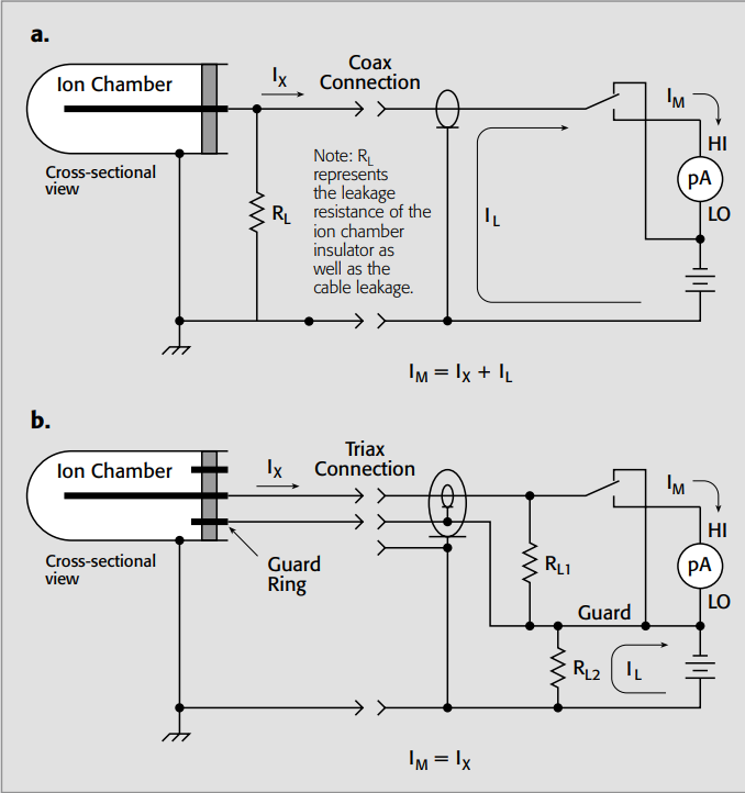
Figure 14. Guarding to reduce leakage currents when switching an ion chamber to a picoammeter
Guarding may also be necessary to prevent leakage current in low current test fixturing.
Electrostatic Interference
Shielding is required because high impedance circuitry is susceptible to pickup of spurious radiated noise. Relay contacts should be shielded from the coil to minimize induced noise from the relay power supply. The DUTs and interconnect cabling should also be shielded to prevent noise pickup. Any good conductor can be used as a shield. All shields should be connected to circuit LO.
Triboelectric Currents
Triboelectric currents are generated by charges created by friction between a conductor and an insulator, such as between the conductor and the insulation of a coax cable. This noise source can be reduced by using special low noise cable that has a conductive coating (such as graphite) and securing the interconnect cabling to minimize movement.
Electrochemical Currents
Electrochemical currents are generated by galvanic battery action caused by contamination and humidity. Thorough cleansing of joints and surfaces to remove electrolytic residue, including PC etchants, body salts, and processing chemicals, will minimize the effect of these parasitic batteries.
Settling Time
When a relay opens or closes, there is a charge transfer (on the order of picocoulombs), which causes a current pulse in the circuit. This charge transfer is due to the mechanical release or closure of the contacts, the contact-to-coil capacitance, and the stray capacitance between signal and relay drive lines. After a relay is closed, it’s important to allow sufficient settling time before taking a measurement. This time can be as long as several seconds. If a step voltage is applied to the circuit, a transient current is generated. This current will gradually decay to a steady value. The time needed to reach the steady value, or the settling time, can be used to determine the proper delay time for the measurement. See Keithley’s Low Level Measurements Handbook for more detailed discussions of generated currents and guarding.
Low Current Matrix Switching
Some low current applications require switching through a matrix. This is often the case when switching several Source-Measure Units (SMUs) to multipin devices or wafer level semiconductor measurements. All the special techniques used to minimize interferences for low current multiplexing also apply to low current matrix switching. However, offset current and leakage current are the types of interference most frequently encountered. In general, low current matrix switching can become complex and is best explained by illustration.
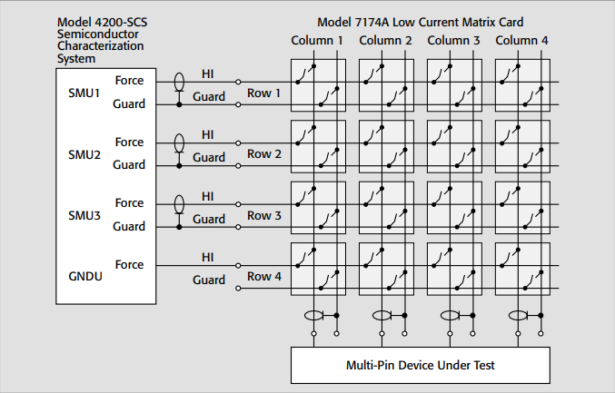
Figure 15 shows three SMUs from the Model 4200-SCS Semiconductor Characterization System connected through a two-pole matrix (Model 7174A Low Current Matrix Card) to a multipin device. Notice that the FORCE terminal of each SMU is connected to the HI terminal of the switch and the Guard of the SMU is connected to the Guard terminal of the switch. In this example, guarding becomes important to avoid leakage currents because the FORCE terminal of the SMU is at the test potential. With the guard terminal at the same potential, the leakage current through the switch is minimized. Guarding will also speed up the response time. The ground terminal (GNDU) of the Model 4200-SCS is connected to asingle row of the matrix.
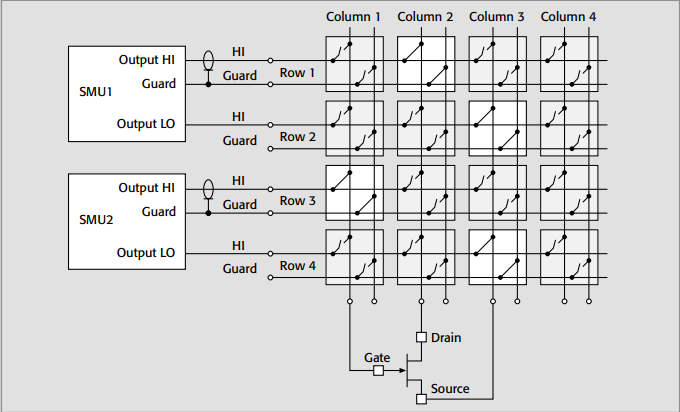
Figure 16 shows two independent SMUs with the Output LO terminals connected to separate rows. Note that each pin of the device under test, the FET, is connected to a single column. The guard terminals of the matrix card are not connected to the device. To connect the SMUs to the transistor, close crosspoint Row 1/Column 2 to connect SMU1 to the drain, Row 3/Column 1 to connect SMU2 to the gate, and Row 2/Column 3 and Row 4/Column 3 to connect both SMU Output LO terminals to the source terminal of the FET.
Remote sensing may be necessary if the current through a given path is high enough to cause a significant voltage drop. Remote sensing compensates for test lead and switch voltage drops and ensures that the programmed output voltage of the SMU is delivered to the load. Remote sensing allows making accurate load voltage measurements. Figure 17 shows SMU1 connected to four rows to enable remote sensing, thereby allowing accurate measurement of the collector-emitter voltage of the BJT. SMU2 is used to supply the relatively small base current and requires only two rows. To connect SMU1 between the emitter and the collector, close crosspoints Row 1/Column 4, Row 2/Column 5, Row 3/Column 2, and Row 4/Column 1. Note that remote sensing requires the use of four rows and four columns. To connect SMU2 between the base and the emitter, close crosspoints Row 5/Column 3 and Row 6/Column 1. Remote sense is not needed to source the base current because the lead resistance does not affect the current.
When connecting two SMUs in a matrix, the Output LO terminals of both SMUs can be tied together and connected to the device using one row. However, the SMU in remote sense may be outputting high current (>1mA) and the resulting voltage drop may interfere with the second SMU if it is used to measure small voltages (<1mV).
Once a given combination of matrix cards, sourcing, and measuring devices is put together, it may be desirable to measure the offset current for various pathways to characterize the system. To measure the offset current, close a specific crosspoint and use an electrometer or SMU to measure the current with everything in place except the device under test. Periodically perform this system check on only the crosspoints for low current switching. If the offset current is relatively constant, this value can then be subtracted from subsequent measurements. Leakage current is another source of measurement interference that must be characterized. It is dependent on the applied voltage, contamination, and humidity.
Leakage current can be determined from path to ground or from path to path. The leakage current can be determined by applying a known voltage and measuring the current between either path to ground or path to path. Once the leakage current in a given pathway is known and remains consistent, it can be subtracted from subsequent measurements. However, humidity and contamination may change the leakage current value over time, so it must be characterized periodically.
Matrix cards suitable for these applications include Models 7152, 7072, and 7174A. All connections should be made with triax cables. Low current matrix cards usually use triax connections to eliminate a possible shock hazard from the guard voltage. Note the outer shield is always at earth ground potential and has been omitted from these figures for clarity.
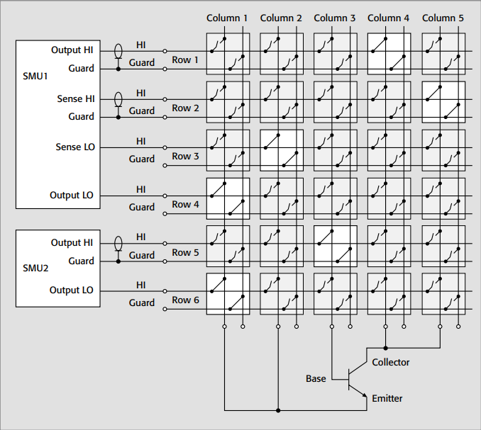
Figure 17. Using two SMUs to test a bipolar junction transistor (BJT)
High Current Switching
When designing a switching circuit for high current (>1A), pay particular attention to the maximum current, maximum voltage, and VA specifications of the switch card. Also, it’s important to choose a switch ard with low contact resistance to avoid excessive heating that can cause contact failure by welding the contacts together. Contact heating is caused by I2R power dissipation.
High current switching can be used for either switching a power supply to multiple loads or for switching an ammeter to multiple sources. Figure 13 is an example of switching a power supply to multiple loads using a multiplexer scanner card. In this example, the power supply will output 1A to each of four loads. This doesn’t present a problem when only oneb channel is closed at a time. However, when all four channels are closed, the power supply will output 4A through the common path. Unfortunately, even though the maximum current of a particular channel is specified at 1A, the common path on the switch card may not be able to tolerate 4A. This is not usually specified for a switch card, but the limitation is usually a function of the trace width and connector ratings. One way to avoid this problem is to use a switch card with independent (isolated) relays and connect with wires rated to carry the total current.
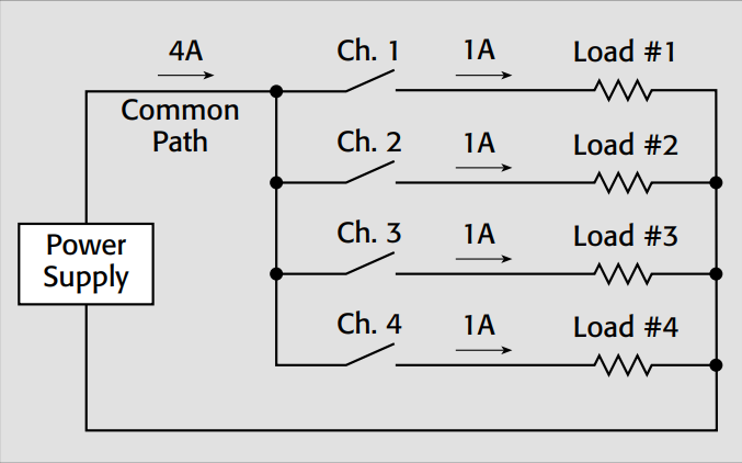
Figure 13. Switching a power supply to multiple loads
When currents that exceed the commercially available card ratings must be switched, then a general-purpose switch card can be used to control external high current relays or contactors. The user must supply the coil current for the external relays.
Under no circumstances should unlimited power (direct from the power line) ever be connected directly to a switch card. When switching high VA loads (power line to motors, pumps, etc.), solidstate relays (SSR) are often used. Industry standard SSR modules are available from many sources. These SSR modules are plugged into a board, such as the Keithley Model PB-24SM, that can be controlled from TTL-level digital outputs. These digital outputs can be from a board that
plugs into a PC or from a scanner mainframe. Some SSR modules can switch up to 1kVA to high power loads.
Concerns about switching transients with reactive loads also apply to high current switching. Cold switching, where contacts do not make or break current or voltage, is recommended for currents in excess of 100mA to avoid radiated interference and to extend relay life.
TestEquity are an approved UK partner for Tektronix
Content produced by Keithley, A Tektronix Company: Test and Measurement Equipment | Tektronix


