

Resistance Switching
Switching an ohmmeter to a device under test is common to a variety of applications, including measuring the insulation resistance of materials, continuity testing of cables and connectors, contact resistance measurements, and measuring the resistance of components such as resistors, thermistors, and potentiometers.
Resistance measurements may range from less than 1Ω to greater than 1012Ω, so the switching techniques required may vary significantly based on the magnitude of the resistance. Low resistance measurements are generally those less than 100Ω, mid-range are those from 100Ω to 107Ω, and high resistance measurements are those greater than 107Ω. As with any measurement, the exact point at which low resistance techniques should be used depends upon the desired measurement accuracy. For
example, a 1ppm measurement of a 1kΩ resistor implies an uncertainty of less than 1mΩ, which can only be achieved by using a four-wire technique.
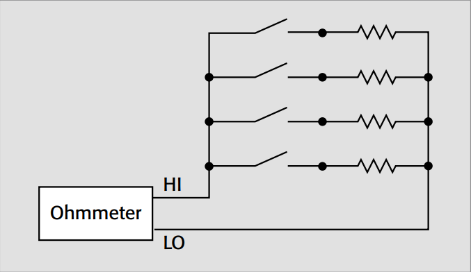
For scanning resistances in the mid-range (100Ω to 10MΩ), either single-ended (one-pole) or differential (two-pole) methods can be used. The single-ended method is shown in Figure 18a. Note that all the resistors under test have a common terminal that is connected to meter low.
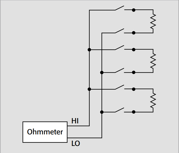
Figure 18b illustrates the differential method. A two-pole relay is used to connect both terminals of the unknown resistor to the meter. The application usually dictates whether the single-ended or differential method should be used for switching. The advantage of the single-ended method is that it requires only half as many switches as the differential method. The only advantage of the differential method is that the offset voltages of the two switches tend to cancel each other. However, given that these are microvolt-level voltages, the differential method is not usually an issue for mid-range resistance switching.
Low Resistance Switching
Applications such as contact resistance measurements and cable continuity testing typically involve switching low resistances. Low resistance (<100Ω) switching requires using techniques that are normally unnecessary for mid-range or high resistances. Offset compensation and remote sensing are techniques often used to eliminate errors due to the switch contact resistance.
Offset Compensation
Spurious microvolt level signals are often present in low resistance circuits, most often as a result of thermoelectric effects. If dissimilar metals are present, a temperature differential across the circuit can easily add several microvolts to the measurement circuit. Switches in the circuit may also add up to several microvolts of error voltage to the measurement. This error voltage is known as contact potential or offset voltage.
Offset compensation will eliminate the switch contact potential, as well as any thermoelectric voltage offsets in the entire measurement circuit. Offset compensation requires making two voltage measurements with two different but known currents. Most often, the second current is of the same magnitude but opposite polarity as the first. The resistance is calculated by dividing the difference between these two voltage measurements by the difference between the two source currents. This procedure will cancel the offsets. In applications where timing is critical, offset compensation may not be practical, because it takes twice as long to make a measurement.
Some DMMs provide a built-in offset compensation capability. Two measurements are made, one at a positive current and another at nearly zero current. The DMM then calculates the resistance automatically.
Four-Wire Switching
Accurate measurements of low resistance in a system require a four-wire connection to eliminate both lead wire and switch contact resistance. Figure 19 is an example of four-wire switching. In this diagram, two of the leads (HI and LO Source) supply current to the resistors, while the other two leads (HI and LO Sense) measure the voltage developed across the resistors. The source leads are connected to one bank of switches and the sense leads are connected to the other bank of switches.
To measure the resistance of the first resistor (R1), channels 1 (Ch. 1) and 4 (Ch. 4) are both closed. The actual resistance measurement is made with either a DMM or a micro-ohmmeter with four-wire ohms capability, with a separate current source and voltmeter, or with a single source-measure instrument.
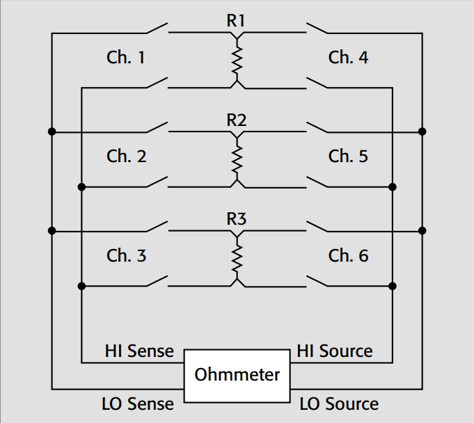
As shown in Figure 19, two sets of two-pole relays are used for low resistance switching. The poles in an individual relay will have similar offset voltages. By using these two poles to connect the low voltage signal to the sense terminals of the meter, the offset voltages or the contact potential (as it is specified), will tend to cancel each other. When the sense leads are connected through two different relays to the unknown resistor (R), as shown in Figure 20a, the offsets are not likely to cancel and may actually combine to cause an even greater error. Even a properly connected two-pole switch, like that shown in Figure 20b, will have some differential offset voltage that will not cancel out. The error caused by such offset voltage can be virtually eliminated by using offset compensation.
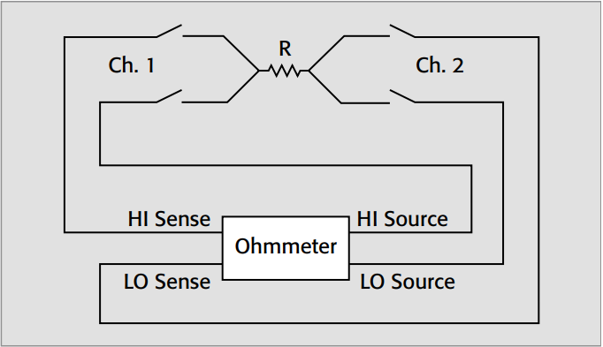
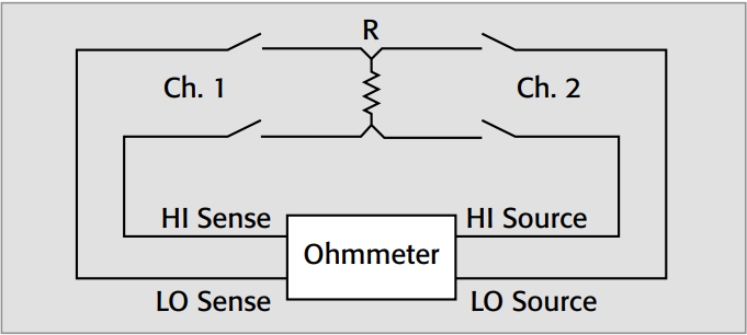
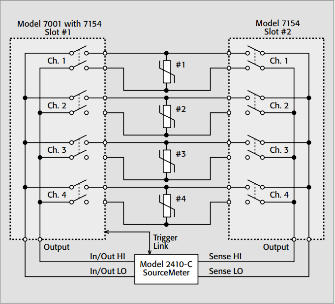
Figure 21 shows an example of the preferred connection scheme when testing metal-oxide varistors. The Model 2410-C SourceMeter® instrument is ideal for testing MOVs because of its ability to source up to 1100V at 21mA. One Model 7154 High Voltage Card connects the source lines to the devices and another Model 7154 connects the sense lines. The twopole relays minimize lead resistance and voltage drop in the switch. This is particularly important when measuring relatively small voltages (millivolts).
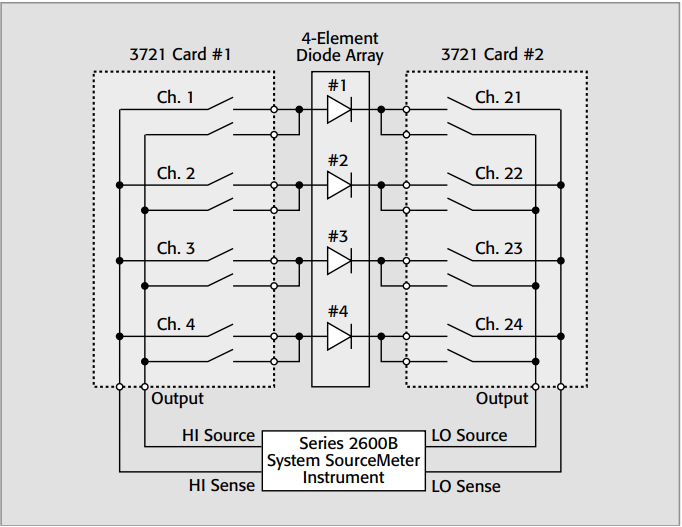
On the other hand, the example of Figure 22 minimizes lead resistance only. With the HI leads and LO leads on the same two-pole relays, offset voltages in the Model 3721 multiplexer switches will not cancel each other because very little current flows in the high impedance sense leads. Depending on the needs of the application, the offset voltages can be addressed with the offset-compensated ohms feature of the Series 2600B System SourceMeter instrument.
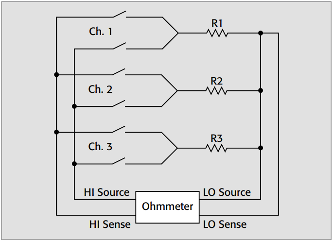
In some applications, the resistances to be tested may have a common terminal. In this case, only one two-pole switch per resistor is necessary, as shown in Figure 23. This approach has the advantage that only half as many switches are required, so it is more economical. The disadvantage is that the offset voltage of the single pole in the sense circuit is added to the measurement. Switching only a single sense lead will not cancel the offset voltage as happens when both sense leads are switched through the same two-pole relay. However, offset compensation will generally correct for this error source at the cost of increased measurement time. Some ohmmeters provide this feature, including two Keithley product configurations, the Model 2700 DMM/Switch Mainframe with the Model 7701 32-Channel Differential Multiplexer Card and the Model 3706A System Switch/ DMM with the Model 3721 Dual 1×20 Multiplexer Card. This feature is known as “common side ohms.” When operating in common side ohms mode, each instrument has the ability to recognize the appropriate card and convert the two-wire connection into a four-wire measurement.
Other Issues
Some low resistance applications may require sourcing a relatively high test current and measuring very low voltages. This may require using a high current switch card for sourcing and a low voltage switch card for measuring.
When switching low impedances, shielding needs are minimal. Shielding is generally needed only in electrically noisy environments.
High Resistance Switching
Applications such as measuring capacitor leakage, multi-conductor cable insulation resistance, and pin-to-pin leakage of connectors require measuring high resistances through switches. Special techniques are required for switching resistances greater than 10MΩ. Different high resistance switching techniques will be needed, depending on whether the source voltage/measure current or the source current/measure voltage method of determining resistance is used. However, techniques such as shielding and guarding apply to both methods.
Source Voltage/Measure Current Method
This technique for measuring high resistance involves sourcing a known voltage, measuring the resulting current, and calculating the resistance. As shown in the schematic in Figure 24, one side of each resistor is connected through a set of switches to the picoammeter (pA), while the other end is connected through a second set of switches to a DC voltage source. To measure the resistance of R1, close switches Ch. 1 and Ch. 4.
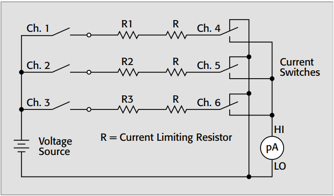
If the measured current is less than 100nA, the switches used to connect the resistors to the picoammeter must have low offset current and high isolation resistance. In many cases, a Form C switch is preferred. The Form C switch keeps one end of the device under test at guard potential (approximately 0V) when the switch is de-energized. This prevents leakage current across the relay that would degrade the measurements. The Form C switch also allows the device under test to be charged for a controlled time interval before measuring.
General-purpose switches are usually sufficient for switching the voltage source unless high voltages (>100V) are involved, in which case, high voltage switch cards are necessary. If high voltage is used, current limiting resistors are needed to avoid damage to the current switches in case the device under test breaks down. The current limiting resistor (R) is placed in series with the device under test. The value of this resistor is chosen such that, in the event of device failure, the short circuit current will not exceed the maximum current specification of the relays on either set of switch cards. The voltage rating of these resistors must be at least equal to the test voltage.
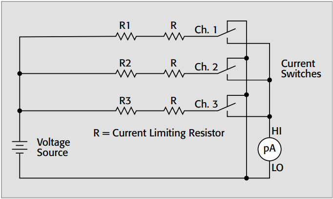
In some cases, the device under test may have a common terminal, as shown in Figure 25. In this case, the voltage source will be applied to all the devices simultaneously. As a result, the excitation voltage time is different for each resistance to be measured. This will cause errors for some time-dependent applications, such as measuring insulation resistance or capacitor leakage. In these cases, the measured resistance is a function of the excitation time.
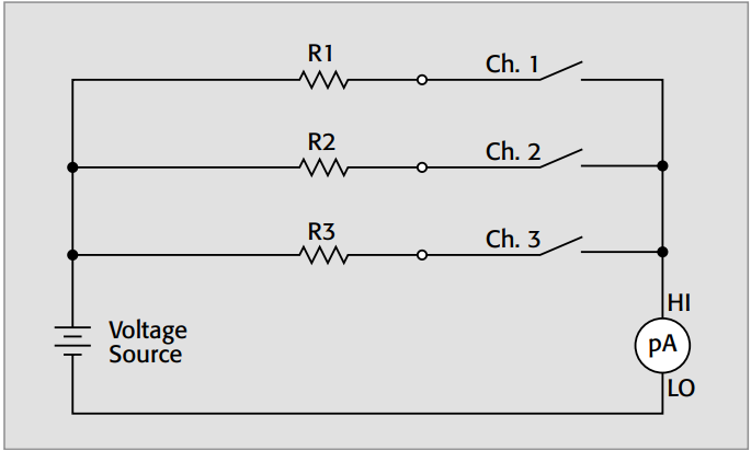
When the measured current is large compared to the relay current offset specification, then Form A switches can provide a more economical solution, as shown in Figure 26. In this example, the leakage current of all open relays will contribute to the measured current. Unfortunately, this leakage current cannot be guarded. Also, if there is a leakage path between devices (as when measuring the insulation resistance between traces on a circuit board or multi-conductor cable), this will also degrade measurement accuracy. In this diagram, each of the resistors has one end connected together to the voltage source. In this case, voltage source switching is unnecessary, because the device under test cannot
be pre-charged.
Special techniques must be used to minimize interferences such as offset currents, leakage currents, electrostatic interference, triboelectric currents, and electrochemical currents. These sources of errors may be due to the switch card or the connecting test fixturing.
Source Current/Measure Voltage Method
In some cases, high resistance is measured by sourcing a current and measuring the resulting voltage. Although this is not the preferred method for measuring high resistance, it is necessary for some applications, such as van der Pauw resistivity measurements of semiconductors. High impedances are being switched, so some of the same switching techniques used when switching low current and high impedance voltages are equally applicable here. To avoid errors, choose a card with low offset current and high isolation resistance. Shielding is necessary to prevent noise due to electrostatic interference.
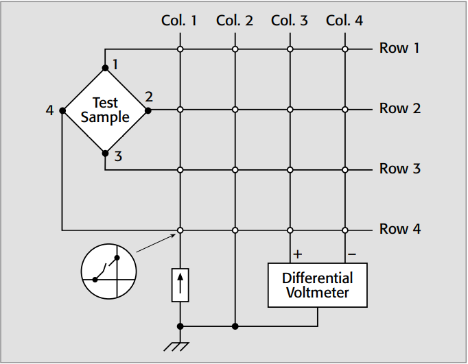
Figure 27 shows a simplified van der Pauw resistivity measurement with a current source and a differential voltmeter. By closing crosspoints Row 1/Column 1 and Row 2/Column 2, the current source is connected to sample terminals 1 and 2. Closing crosspoints Row 3/Column 3 and Row 4/Column 4 will connect the voltmeter between terminals 3 and 4. For more detailed information on van der Pauw resistivity measurements, consult Keithley’s Low Level Measurements Handbook.
TestEquity are an approved UK partner for Tektronix
Content produced by Keithley, A Tektronix Company: Test and Measurement Equipment | Tektronix


